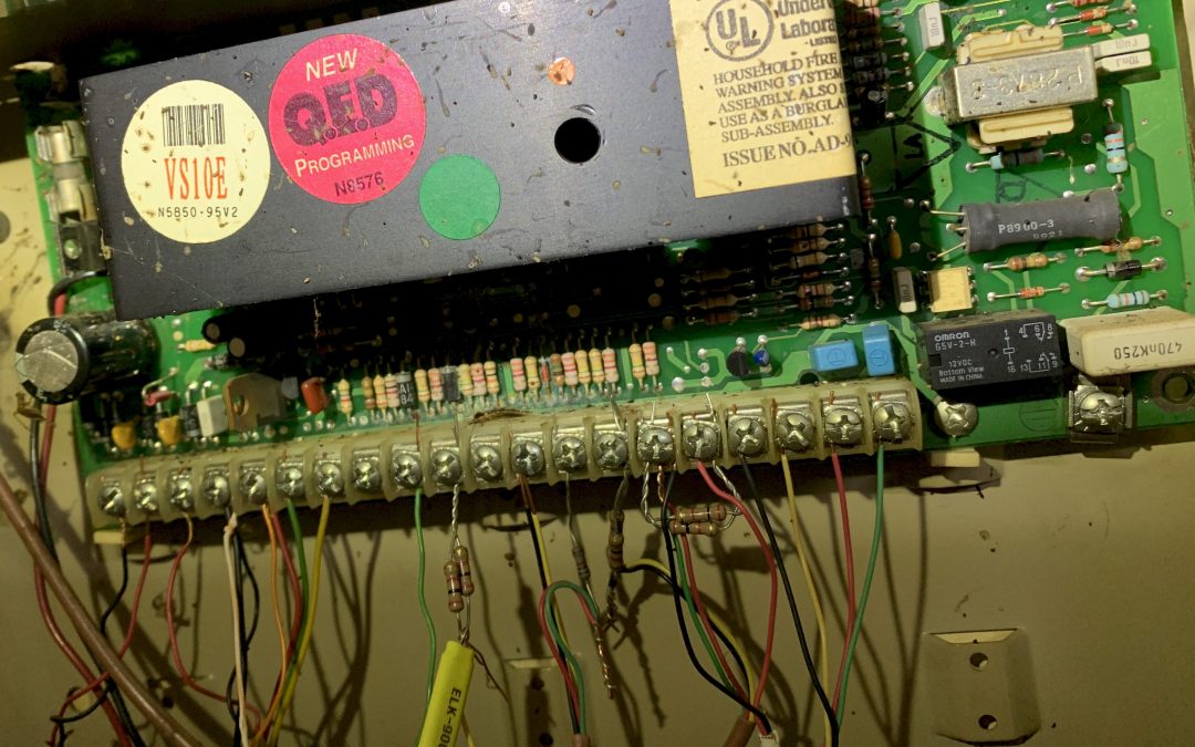
Just because you hired a professional installation company to install your alarm system doesn’t mean they will install your system in a professional manner.
One of our sales representatives was asked to consult a customer about taking over the monitoring of their system. He took the following picture of the existing system installed by a licensed company. We were able to point out several violations of the manufacturer’s instructions and fire code. How many do you see?
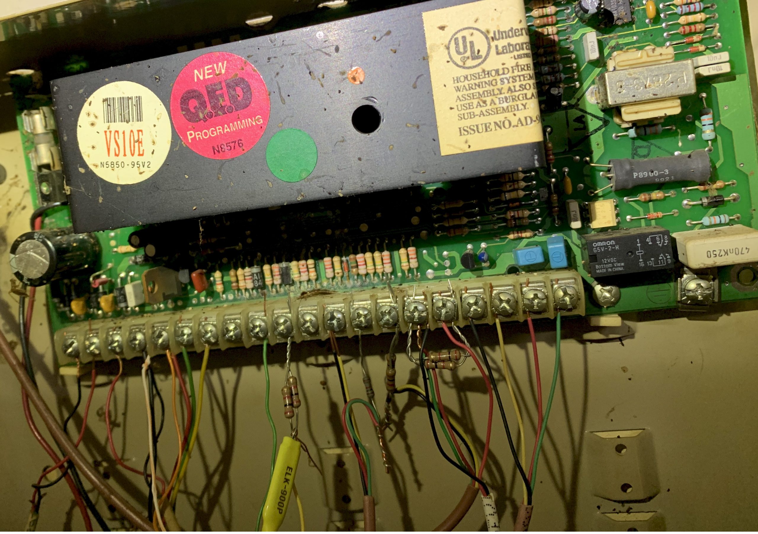
Using colored arrows, we want to point out the violations of the manufacturer’s instruction. However, we also pointed out that this system is still communicating on a landline. We also recommended to this customer to upgrade their communication technology to cellular, network, or both. We also recommended that they allow us to replace the wire used to power the system from the Class 2 transformer from the existing 22AWG wire (the far left wire and two terminals) to 18AWG wire, as it is the industry standard. This is indicted by the blue arrow below.
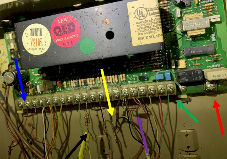
Black arrow – indicates resisters NOT at the end of line, as per manufacturer’s instructions. They also used B-type connectors which is an inferior way to splice wires. Guard Tronic uses solder and tape for all splice connections.
Yellow arrow – points to wires twisted together. No B-type connector. No solder and tape or shrink tube. No protection from corrosion or way to protect the connection from shorting to the metal of the box the panel is mounted in. This is also another example of resistors NOT at the end of line.
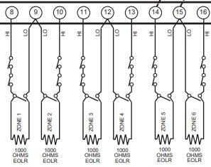
Purple arrow – points to resisters tied together and mounted in the panel and NOT at the end of line. This is especially dangers as these wires go to a normally open device, such as a robbery / hold up device or fire alarm initiating device. The image below is from the instruction manual of the control panel and shows the resistors must be mounted at the end of line.
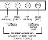
Green arrow – as mentioned above, this panel is still trying to use telephone lines to communicate to the alarm company’s monitoring facility. We will always recommend multiple paths of communication and that our customers should be moving away from digital communicators to a more modern form, such as network or cellular communicators. The company also failed to install a RJ31X jack and phone cord in accordance with manufacturer’s instructions and telephone company tariffs (see image below).
Red arrow – points to where the earth ground should be terminated on the control panel.
(see image below)


